
A Tardis clock with an RGB LED
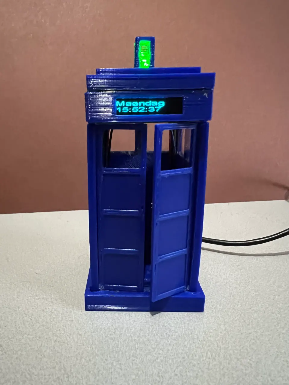
A Tardis with doors that open, so you can keep something inside. It’s also a clock, and on top sits an RGB LED you control from outside, for example when a new email or chat message comes in.

What you need
- A small OLED screen
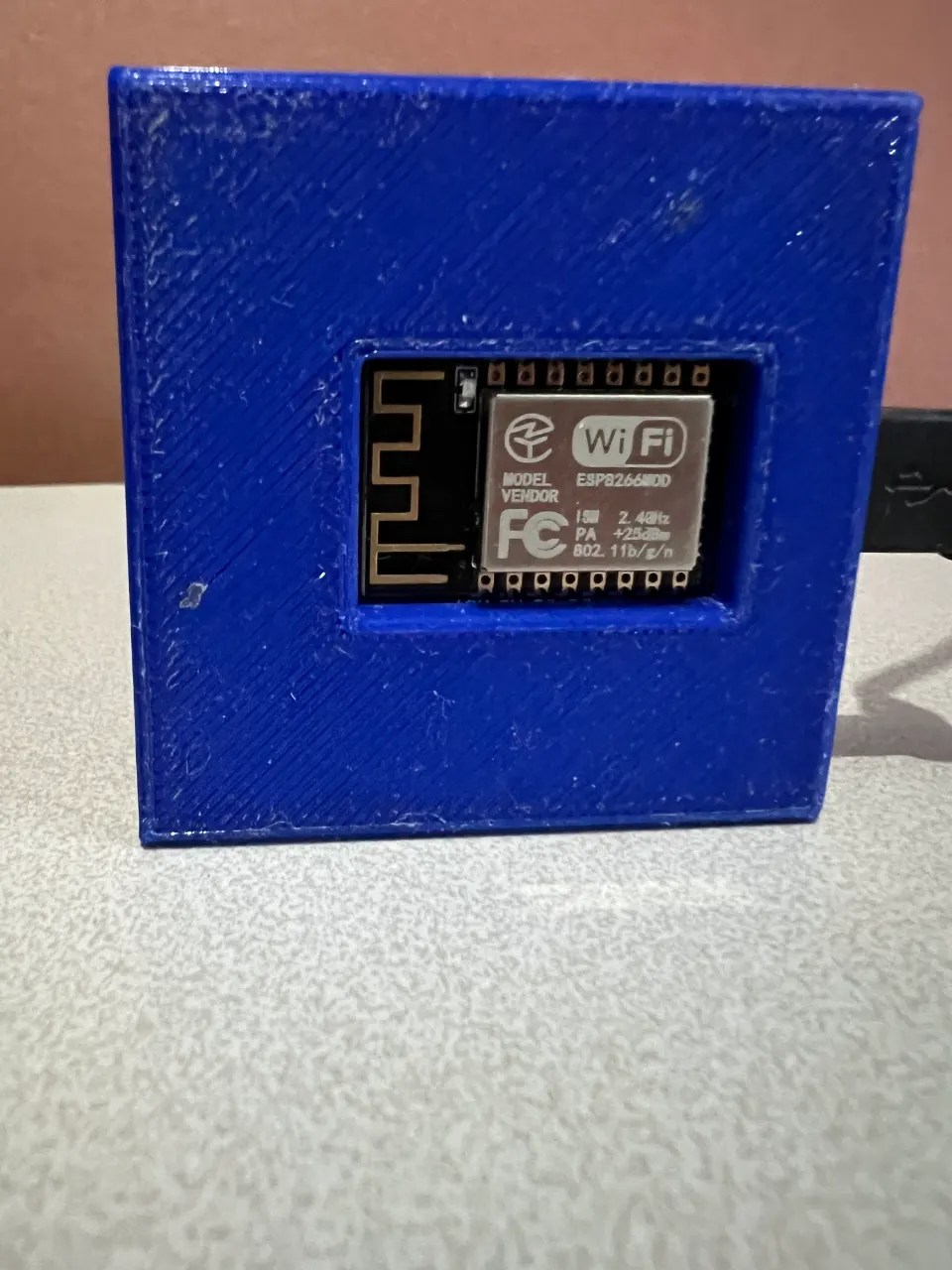
- An ESP8266 board (Wemos D1 mini)
- An RGB LED
Software
The Tardis is driven by a small microcontroller with Wi-Fi. Another board works too, such as an ESP32 or an Arduino with an Ethernet shield. I wrote the firmware in PlatformIO, but any other development environment will do.
To connect the Tardis to your Wi-Fi and to the API for the LED, change these lines in
main.cpp:
const char* ssid     = "SSID_HERE";
const char* password = "PASSWORD_HERE";

String tardisAPI = "API_URL_HERE";
Once the firmware is on the board, the microcontroller calls the API every second. The
API replies with JSON containing the key led and a value from 1 to 5:
- green, blinking
- green, steady
- blue, blinking
- blue, steady
- LED off
A reply looks like this, for example:
{
  "led": 3
}
If the LED blinks red, the Tardis has no Wi-Fi. If it’s steady red, the API’s reply isn’t valid JSON.
Enclosure
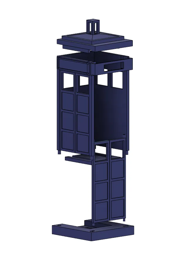
I printed the enclosure in blue PLA, but other materials work too. The STL files are in the download at the end of this post.
You glue the parts together. That was a deliberate choice: this way nothing needs to be printed on supports. Fix the electronics in place with hot glue, for example. For the “glass”, I stuck a piece of plastic from old packaging to the inside of the walls.
Electronics
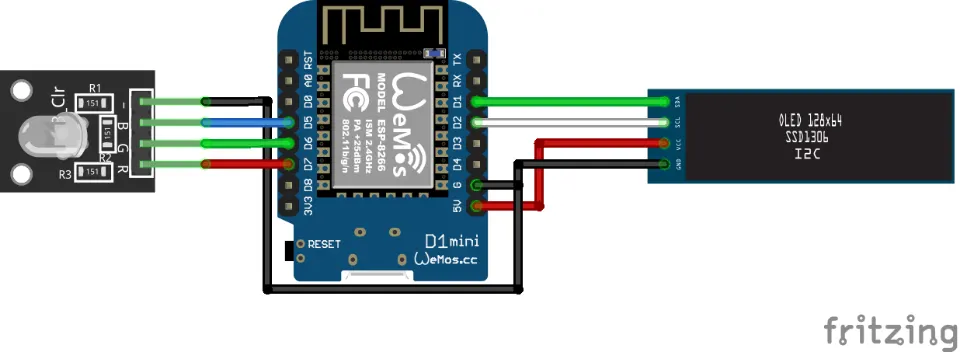
Connect everything to the microcontroller like this:
- D5 → red of the RGB LED
- D6 → green of the RGB LED
- D7 → blue of the RGB LED
- D1 (SCL) → SCL of the OLED screen
- D2 (SDA) → SDA of the OLED screen