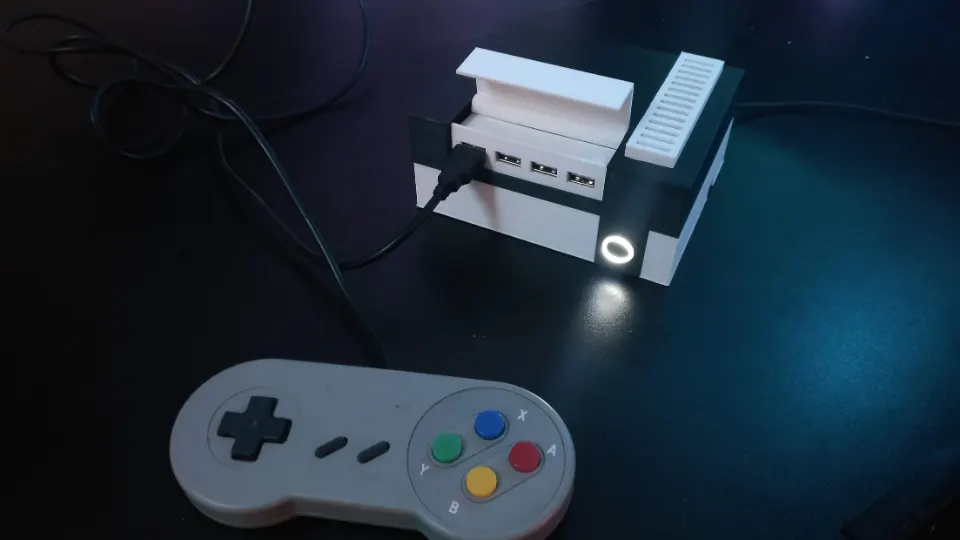

A game console with a motor-driven lid
Ever wanted to build your own game console? I made a case for a Raspberry Pi running RetroPie, an operating system that emulates classic consoles. The lid opens with a motor.
What you need
- A Raspberry Pi
- An SD card of at least 8 GB
- The printed case (STL files in the download)
- A 5V illuminated push button (angel eye)
- A 4-port USB hub
- A 5V stepper motor with a ULN2003 driver
- Two pulleys and a timing belt, for example from a 3D printer
Software
RetroPie
First install RetroPie on the Raspberry Pi. The RetroPie installation guide explains how.
The motor script
The lid is driven by a Python script. There are several ways to start it; I use a cron job that runs the script as soon as the Pi boots.
Log in to the Raspberry Pi over SSH. You’ll need an SSH client and the Pi’s IP address,
which you can find in your router. The default username is pi and the
password is raspberry.
Then create the script:
sudo nano /home/pi/script.pyPaste in the contents of the script from the download, and save with Ctrl+X, Y and Enter. Then open crontab:
sudo crontab -eIf you’re asked to pick an editor, choose nano. Add this line:
@reboot python /home/pi/script.py &Save with Ctrl+X, Y and Enter.
Case
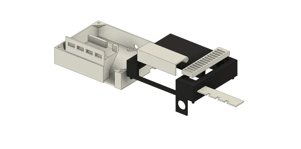
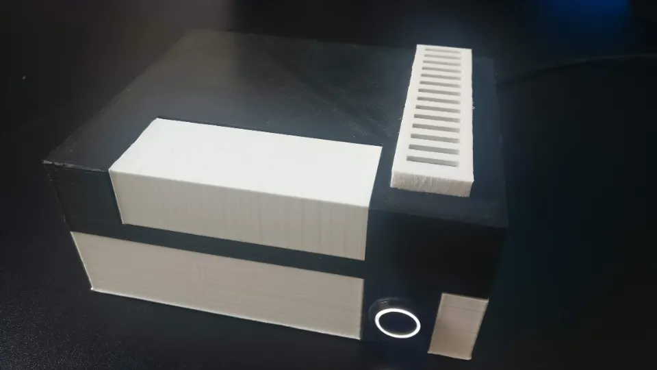
I printed the case in black and white PLA, but other materials work too. The STL files are in the download at the end of this post.
To mount the electronics, I melted threaded inserts into the standoffs with a soldering iron. The motor goes in the top of the case. Then fit the pulleys onto the motor and cut the belt to length.
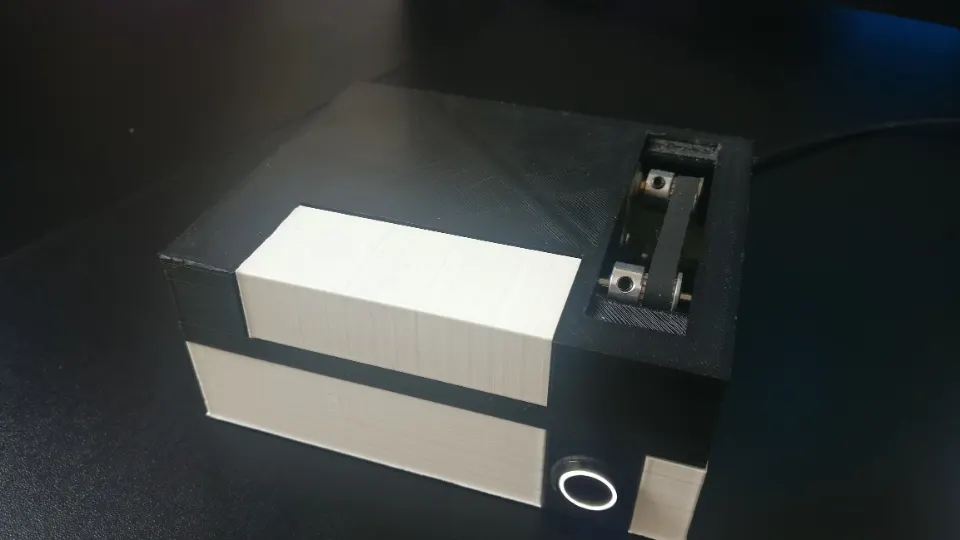
Electronics
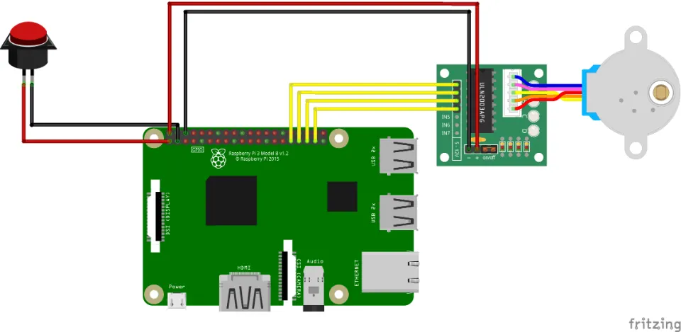
Connect everything like this:
- The push button to GPIO 2 and 3.3V. If your button has a light, connect it to the right voltage too (5V in my case).
- The stepper motor driver: IN1 → GPIO26, IN2 → GPIO19, IN3 → GPIO13, IN4 → GPIO6.
- The USB hub to one of the Raspberry Pi’s USB ports.