
A docking station built into my desk
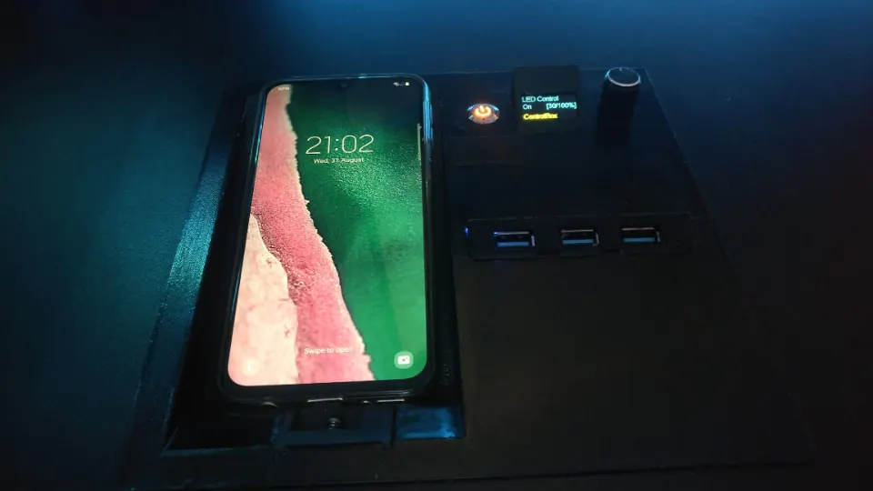
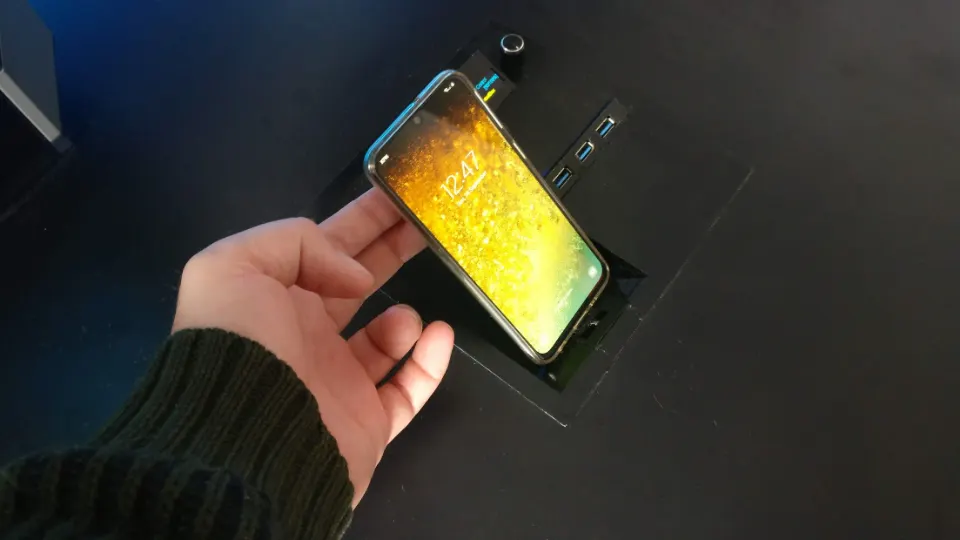
A docking station set into your desktop. From one spot you charge your phone, switch your computer on or off and control the LED strip, which turns on and off with the computer.
What you need
- A 5V illuminated push button (angel eye)
- A small OLED screen
- An ESP8266 board (Wemos D1 mini)
- A USB hub
- A right-angled USB-C adapter and a USB to USB-C cable
- A rotary encoder with push button
- Female Dupont wires
Software
The docking station is driven by a small microcontroller with Wi-Fi. Another board works too, such as an ESP32. You flash the firmware with a micro USB cable; there’s an opening for it at the top of the enclosure.
I wrote the firmware in PlatformIO, but any development environment that supports
Arduino code will do. The code is in main.cpp, in the download at the end
of this post.
The top of that file lists which pins are used for what. If you want to use different
pins, change them there. Also check NUM_LEDS: the number of LEDs on your
strip. I use a strip with the WS2812B chip; if yours is different, change that at the
top as well.
The firmware switches the LED strip on or off based on two things:
- the signal from the computer (
PC_STATUS); - the rotary knob.
When the strip is on, turn the knob left or right to change the brightness.
Enclosure
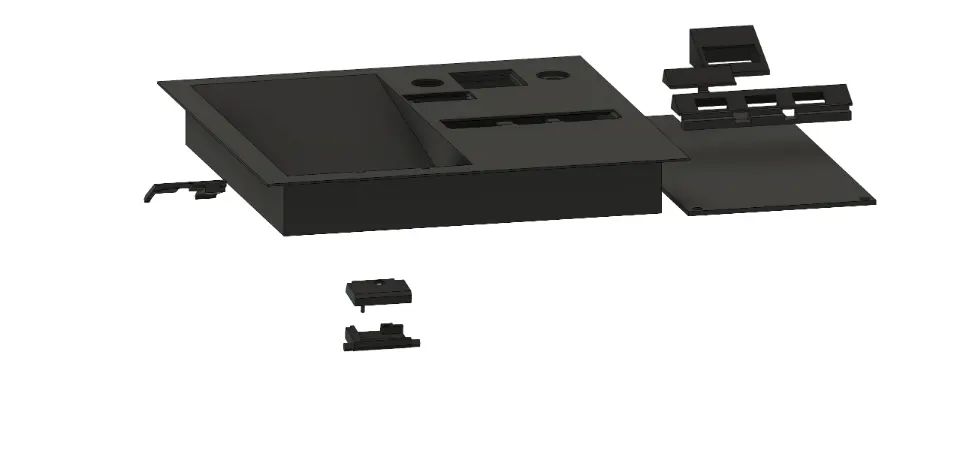
I printed the enclosure in black PLA, but other materials work too. The STL files are in the download.
The main parts are screwed together, into threaded inserts that I melted into the plastic with a soldering iron. The smaller parts are glued on, so nothing needs to be printed on supports. Fix the electronics in place with hot glue, for example.
The USB-C adapter sits in its own printed housing. A small spring (from a pen, for example) keeps it in place while still letting it move up and down a little.
Electronics
Connect everything to the microcontroller like this:
- D0 → the LED header on the motherboard (computer status). My computer outputs 5V there, so I converted it to 3.3V.
- D3 → the knob’s push button (10k resistor to the supply)
- D5 → pin A of the knob (10k resistor to the supply)
- D6 → pin B of the knob (10k resistor to the supply)
- SDA → SDA of the OLED screen
- SCL → SCL of the OLED screen
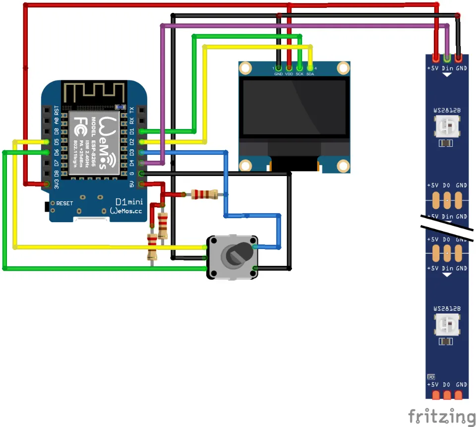
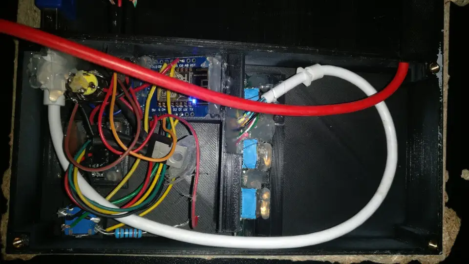
The power button. This depends on the type of button. With mine, I could connect the LED’s plus and minus straight to the motherboard, and the NC contact directly to the motherboard’s power switch header.
The USB hub. I removed its casing and used only the small board with the USB ports. A USB cable on it plugs straight into your computer.
The connection to the computer. I glued two female headers into the enclosure, one with 3 pins and one with 4. A cable from the motherboard plugs into the 4-pin header. The 3-pin header carries power and the data signal for the LED strip.